Hi Gene, and welcome to our Forum.
Your plan using an MCU output pin to emulate an RPM sensor is interesting and feasible without great effort. The throttling of the MCU output frequence is mandatory to stay within the range of 50 - 5KHz for the Caliper2PC S1 / S2 sensor sockets inputs.
In order to avoid damages, short circuits, false voltages etc. on the MCU and / or on the Caliper2PC interface, please use an optocoupler. The MCU output pin will drive the IR LED. A resistor must be used in series with the IR LED to limit the current to the working point of the LED (e.g. 10 mA). Please check that your MCU can deliver the current needed by the optocoupler's IR LED.

The optocoupler's transistor can be connected to the to the Caliper2PC interface the same way you would connect an ordinary optical sensor. Please follow the pin assignment for the transistor according to the picture attached.

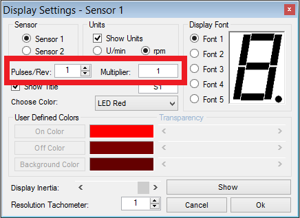
Within the Caliper2PC software's Tachometer settings window the pulses / revolution and the multiplier can be set to fit the pulses generated by the MCU to your spindle's RPM.

Some pictures of your project will be very much appreciated.
Your plan using an MCU output pin to emulate an RPM sensor is interesting and feasible without great effort. The throttling of the MCU output frequence is mandatory to stay within the range of 50 - 5KHz for the Caliper2PC S1 / S2 sensor sockets inputs.
In order to avoid damages, short circuits, false voltages etc. on the MCU and / or on the Caliper2PC interface, please use an optocoupler. The MCU output pin will drive the IR LED. A resistor must be used in series with the IR LED to limit the current to the working point of the LED (e.g. 10 mA). Please check that your MCU can deliver the current needed by the optocoupler's IR LED.
The optocoupler's transistor can be connected to the to the Caliper2PC interface the same way you would connect an ordinary optical sensor. Please follow the pin assignment for the transistor according to the picture attached.
Within the Caliper2PC software's Tachometer settings window the pulses / revolution and the multiplier can be set to fit the pulses generated by the MCU to your spindle's RPM.
Some pictures of your project will be very much appreciated.

